Plugin Overview
Dip-Strike Tools is a QGIS plugin that aims to provide a set of tools for digitizing, managing, and analyzing plane orientation or attitude data (dip and strike) of planar geologic features. It currently provides basic tools to streamline the workflow for geologists working with structural geology datasets, enabling efficient dip and strike data capture and management within QGIS.
What are Strike and Dip?
Strike and dip are fundamental measurements in structural geology that describe the orientation of planar geological features such as rock layers, fault planes, and fractures. The dip is the angle the slope descends, while the direction of descent can be represented by either strike direction or dip direction.

Schematic depiction of “strike” and “dip” in structural geology. Z: strike line of the red plane, σ: strike angle, F: dip direction, φ: dip angle. (https://en.wikipedia.org/wiki/File:Streichbild.svg)
Note
Key Definitions:
Strike or Strike line: a line representing the intersection of a planar feature with a horizontal plane
Strike Azimuth or Strike direction: The compass direction of the strike line (0-360°)
Dip or Dip angle: The angle of inclination of the planar feature from horizontal (0-90°)
Dip Azimuth or Dip direction: The compass direction of the steepest descent down the plane (perpendicular to the strike line)
On geological maps, strike and dip can be represented by a T symbol with a label that gives the dip angle, in degrees, below horizontal. The longer line represents strike, and is in the same orientation as the strike angle. Dip is represented by the shorter line, which is perpendicular to the strike line in the downhill direction. Strike and dip information recorded on a map can be used to reconstruct various structures, determine the orientation of subsurface features, or detect the presence of anticline or syncline folds.

Common map symbols (https://en.wikipedia.org/wiki/File:Guide_to_common_map_symbols.svg)
Dip and strike data collection and representation
In GIS-based geological mapping, strike and dip are typically represented as point features with associated numerical attributes for strike and dip. These points are then styled using appropriate symbology to visually communicate the orientation of planar features on the map.
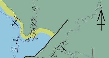
Example of dip/strike representation on map
When entering data, geologists often need to determine the correct azimuth for strike or dip directions, or convert between strike and dip azimuths. These calculations can be tedious and prone to error if done manually.
A common scenario is the digitization of data from scanned historical (cartaceous) geological maps. In these cases, the dip angle is often provided as a label next to the strike and dip symbol. However, the strike or dip azimuth is usually not explicitly stated and must be determined manually by measuring the orientation (azimuth) of the strike line depicted on the symbol. This manual process can be time-consuming and prone to error, especially when working with large datasets.
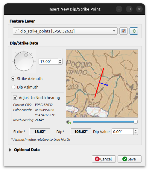
Inserting a new dip/strike feature
The Dip-Strike Tools plugin streamlines these tasks by providing intuitive tools for data entry and conversion. It automates common calculations, reduces the risk of mistakes, and helps ensure that your geological data is both accurate and consistently formatted. The plugin is designed to grow, with future updates planned to add more advanced tools for data management and geological analysis.
“True” north and grid convergence
A bearing (or azimuth) is a clockwise angle measured from North to a direction of interest. However, “North” can refer to different reference directions depending on context:
Grid north is the direction of the map’s vertical (south-to-north) grid lines, defined by the map projection.
True north is the direction along the Earth’s surface towards the geographic North Pole (the local meridian).
Magnetic north is the direction a compass needle points, towards the Earth’s magnetic pole.
Note
Magnetic declination is the angle between magnetic north and true north. For most geological mapping, this angle is small and does not significantly affect dip/strike measurements, so the plugin does not account for it.
The grid convergence (or meridian convergence) is the angle between true north and grid north at a specific location. This angle varies depending on your position on the map and the map projection in use.
When determining the dip or strike azimuth for a feature in QGIS, the plugin can automatically account for local grid convergence, applying the necessary correction to convert between “grid” azimuths (as measured on the map) and true azimuths (relative to true north). This helps ensure that your orientation data is accurate and consistent, regardless of the coordinate reference system or projection used.
Available Tools
The plugin currently provides four main tools accessible from the QGIS toolbar:
1. Create New Dip Strike Layer
Creates and configures new vector layers specifically designed for geological data collection. Supports multiple output formats and automatically sets up required fields.
2. Create Dip Strike Point
Interactive map tool for collecting geological measurements. Click anywhere on the map to record strike/dip data with visual preview and validation.
3. Calculate Dip/Strike Values
Batch calculation tool for converting between strike and dip azimuths in existing datasets. Includes input validation and rounding options.
4. Plugin Settings
Configure plugin behavior and customize geological type classifications for your specific workflow.